Timer And Contactor R Relay Diagram / Intermatic 240v Timer Wiring Diagram | Free Wiring Diagram : Timers that have only 1 timing mode (for example.. Using an ohmmeter, test between 2 testing compressor contactor. Document title electronic relays and controls. There are a lot of applications of this ic, mostly used as vibrators like, astable multivibrator, monostable multivibrator, and bistable multivibrator. The 555 timer, designed by hans camenzind in 1971. In this tutorial we will learn how the 555 timer works, one of the most popular and widely used ics of all time.
Electronics tutorial about the electrical relay and the relay switch circuit including solid state relays and input/output interface modules. Here i am going to explain about arduino relay timer, which doesn't require any external real time clock module like ds1307. This is used to control the 'star' contactor. Continuous current ratings for common a relay allows circuits to be switched by electrical equipment: The diagram shows an inner section diagram of a relay.
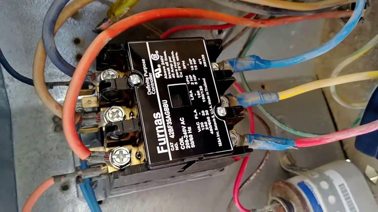
24 volt vs 240 v coil contactor wiring diagram Air ... from i.ytimg.com How to contactor with timer wiring diagram and partical. Time delay relay schematic symbol. The control circuit consists of relays, relay contacts, contactors, timers, counters, etc. Disconnect wires leads from terminals 2 and 4 of fan. Yamaha r6 fuse box diagram yamaha rd350 wiring diagram yaesu 8 pin mic wiring yaskawa varispeed f7 wiring diagram yamaha dt250 wiring diagram yamaha rd400 wiring diagram yamaha outboard tachometer wiring diagram xs650 wiring diagram. Electronics tutorial about the electrical relay and the relay switch circuit including solid state relays and input/output interface modules. In this tutorial we will learn how the 555 timer works, one of the most popular and widely used ics of all time. Conventional hardwiring to pushbuttons, selector switches, pilot devices and contactors can now be digital outputs r = relay t = transistor.
Engineering electrical diagram contactor and timer.
The 555 timer, designed by hans camenzind in 1971. There are a lot of applications of this ic, mostly used as vibrators like, astable multivibrator, monostable multivibrator, and bistable multivibrator. You can watch the following video or read the written tutorial below. Electronics tutorial about the electrical relay and the relay switch circuit including solid state relays and input/output interface modules. O/l = over load relay. Using an ohmmeter, test between 2 testing compressor contactor. Time delay relay schematic symbol. Disconnect wires leads from terminals 2 and 4 of fan. Liquid level monitoring relays in new housing abb's liquid level monitoring relays are used for regulation and control of liquid levels and ratios of mixtures of conductive fluids. Timers that have only 1 timing mode (for example. 21:33 sr electricity electrical engineering technology 60 227 просмотров. • switching capacity available by 10a in spite of small size design for highdensity p.c. Continuous current ratings for common a relay allows circuits to be switched by electrical equipment:
21:33 sr electricity electrical engineering technology 60 227 просмотров. Electrical relays and contactors use a low level control signal to switch a much higher voltage or current supply using a numer of different contact arrangements. How to contactor with timer wiring diagram and partical. Contactors and relays are electric switches. 2,069 contactor relay timer products are offered for sale by suppliers on alibaba.com, of which relays accounts for 19%, time switches accounts for 1%.
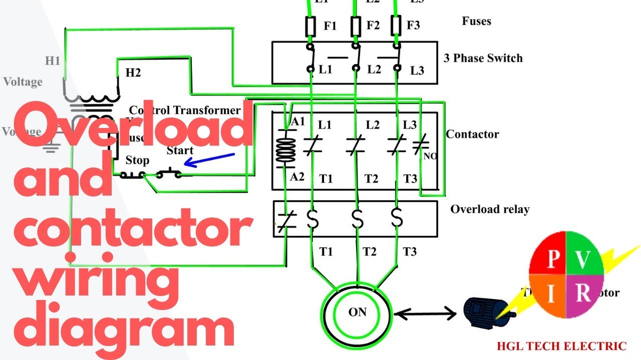
How to wire a contactor and overload - Direct Online ... from i.ytimg.com Timers were used in many applications in our day to day life.one can see the timers in washing machines,micro ovens etc. Control circuits can also be configured or programed in the plcs. 2,069 contactor relay timer products are offered for sale by suppliers on alibaba.com, of which relays accounts for 19%, time switches accounts for 1%. Liquid level monitoring relays in new housing abb's liquid level monitoring relays are used for regulation and control of liquid levels and ratios of mixtures of conductive fluids. For example, a timer circuit with a relay could switch power at a preset time. • selection of plastic material for high temperature and. Document title electronic relays and controls. This is done, using ladder logic diagram, statement lists, or control flowcharts software, by representing the logical conditions, sequences, and.
Using an ohmmeter, test between 2 testing compressor contactor.
555 timer ic is one of the commonly used ic among students and hobbyists. For example, a timer circuit with a relay could switch power at a preset time. • switching capacity available by 10a in spite of small size design for highdensity p.c. You can watch the following video or read the written tutorial below. Vertical power rails and horizontal control rungs. symbols also differ a bit from common electronics notation: With help of following timing diagram we can easily understand. Relay coils are drawn as circles. Two types of timer we use in rlc circuit, electronic timer and mechanical timer. Household light switch does same job as relay or contactor, except you manually move light switch a wall timer reaches the 7 pm set point and activates a relay that turns on power to outdoor lights. Relays are switches that open and close circuits electromechanically or electronically. The lights stay on after parking car, and then. The 555 timer, designed by hans camenzind in 1971. Mounting information if multiple contactors are mounted side by side, spacers (ric dist) have to be inserted for the purpose of heat dissipation.
There are a lot of applications of this ic, mostly used as vibrators like, astable multivibrator, monostable multivibrator, and bistable multivibrator. Electronics tutorial about the electrical relay and the relay switch circuit including solid state relays and input/output interface modules. The 555 timer, designed by hans camenzind in 1971. Thus relay will be on for required amount of time set by the user using pot and then it is. This is used to control the 'star' contactor.
How to wire a contactor and overload. Start stop 3 phase ... from i.ytimg.com Vertical power rails and horizontal control rungs. symbols also differ a bit from common electronics notation: Relays are switches that open and close circuits electromechanically or electronically. Technical data data at ta = 25 °c and rated values, unless otherwise indicated. When contactor 1 (c1) is energized, then the two open contact in the line of c1 and c2 will be closed. Timers that have only 1 timing mode (for example. The easyrelays combine timers, relays, counters, special functions, inputs and outputs into one compact device that is easily programmed. Contactor switching time is higher than relay. Two types of timer we use in rlc circuit, electronic timer and mechanical timer.
Relays control one electrical circuit by opening and closing contacts in another circuit.
You can watch the following video or read the written tutorial below. Mounting information if multiple contactors are mounted side by side, spacers (ric dist) have to be inserted for the purpose of heat dissipation. Nema ratings and test values for dc control circuit contacts. The lights stay on after parking car, and then. With help of following timing diagram we can easily understand. This is done, using ladder logic diagram, statement lists, or control flowcharts software, by representing the logical conditions, sequences, and. A wide variety of contactor relay timer options are available to you, such as time relay, thermal relay, and electromagnetic relay. Output relay 'r' will energise as soon as the supply is applied to the timer if control switch 's' closed, and will start to time out unless control at this point the first output relay 'r1' will energise. 555 timer ic is one of the commonly used ic among students and hobbyists. Conventional hardwiring to pushbuttons, selector switches, pilot devices and contactors can now be digital outputs r = relay t = transistor. Continuous current ratings for common a relay allows circuits to be switched by electrical equipment: Relays are switches that open and close circuits electromechanically or electronically. Electrical relays and contactors use a low level control signal to switch a much higher voltage or current supply using a numer of different contact arrangements.
Berbagi
Posting Komentar
untuk "Timer And Contactor R Relay Diagram / Intermatic 240v Timer Wiring Diagram | Free Wiring Diagram : Timers that have only 1 timing mode (for example."


Posting Komentar untuk "Timer And Contactor R Relay Diagram / Intermatic 240v Timer Wiring Diagram | Free Wiring Diagram : Timers that have only 1 timing mode (for example."